Deliverable 1
Model and Notes on Assembly
 |
| Here is a face view of the yo-yo, showing the bow-tie element. |
Our design is composed of six main elements: the white injection-molded yo-yo body, a ball bearing, a black injection-molded bow-tie, a black injection-molded retaining ring, a pair of nuts, and finally a clear thermoformed window. The main feature of our product is that the bow-tie is free to spin independently of the main body, which will show through the clear plastic window when the yo-yo comes to a stop in the user's hand.
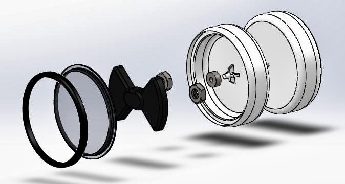 |
| Exploded view showing hidden components. |
The exploded view shows the components that will be hidden from the user, and also shows the order in which the parts will be assembled. The bearing is press-fit to a boss on the yo-yo body, which is screwed into the other half via set-screw and an embedded hex nut. The two nuts shown are press-fit into the bow-tie from the rear to increase its inertia, and then the whole assembly is press-fit to the OD of the bearing using a pocket on the rear of the bow-tie. The window is then put into place over the bow-tie, with its flange resting upon a lip molded into the body. Finally, the retaining ring is pushed into place, creating a press-fit between itself and the outer edge of the body, and trapping the flange of the window, securing the whole assembly together.
The product as a whole satisfies the parts number requirement and also the injection molding and thermoforming requirements. Parts to be injection molded were designed to have near-constant thickness to facilitate even cooling without dishing, buckling, or warping defects. This was especially important on the bow-tie, where the underside comprises entirely of intersecting ribs that form the pockets necessary to install the counterweight nuts and bearing, and also the body, where care was taken to ensure that the shelf for the window and retaining ring did not compromise the wall thickness. Parts were also designed to maintain their shape whilst cooling, for example we added supports to the central boss of the body part so that it would stay perpendicular to the floor of the body pocket to ensure that the bow-tie would be free to spin. Lastly, all parts were designed with tapered faces so that they would not grab the core of the molds used to produce them, thus increasing the speed of our production. Quality, Cost, and Rate dominated our decision-making process during the design of these parts.
Table of Specifications
Specification
|
Value (with units)
|
Measuring Method
|
Yo-Yo
Diameter
|
2.500
± 0.005 inches
|
Digital
Caliper
|
Yo-Yo
Outer-Gap Diameter
|
2.368
+0.000
- 0.005 inches |
Digital
Caliper
|
Yo-Yo
Inner-Gap Draft Angle
|
2
± 2 degrees
|
Digital
Caliper, tangent of two sides
|
String
Gap
|
0.075
± 0.005 inches
|
Digital
Caliper
|
Yo-Yo
Width
|
1.700
± 0.005 inches
|
Digital
Caliper
|
Yo-Yo
Cavity Diameter
|
2.092
± 0.005 inches
|
Digital
Caliper
|
Bow
Tie Max Length
|
2.046
± 0.005 inches
|
Digital
Caliper
|
Bow
Tie Inner Diameter
|
0.375
+0.000
- 0.005 inches |
Digital
Caliper
|
Inner
Shaft (for ball bearing) Width
|
0.125
+0.005
- 0.000 inches |
Digital
Caliper
|
IDE
of Ball Bearing
|
0.125
+0.000
- 0.005 inches |
Digital
Caliper
|
ODE
of Ball Bearing
|
0.375
+0.005
- 0.000 inches |
Digital
Caliper
|
Yo-Yo
Wall Thickness
|
0.1875
± 0.005 inches
|
Digital
Caliper
|
Retaining
Ring Outer Diameter
|
2.378
+0.005
- 0.000 inches |
Digital
Caliper
|
Retaining
Ring Inner Diameter
|
2.175+0.000
- 0.005 inches |
Digital
Caliper
|
Window
Extrusion Outer Diameter
|
2.185+0.005
- 0.000 inches |
Digital
Caliper
|
Mass
of Yo-Yo
|
0.166
pounds
|
Scale
|
Volume
of Yo-Yo
|
4.10
inches cubed
|
Mass/Density
|
Max
RPM of Yo-Yo
|
142.29
RPM
|
Tachometer
sensor
|
Inertia
in X and Y direction
|
0.0952
pounds*inch2
|
Calculations
|
Inertia
in Z direction
|
0.1345
pounds*inch2
|
Calculations
|
Gantt Chart
Go here for the current Gantt chart
No comments:
Post a Comment